BatchTransferPumping
Overview
The BatchTransferPumping class models batch liquid transfer operations using pumps, incorporating pump characteristics, system hydraulics, and fluid dynamics. This model is essential for batch processing operations where liquids need to be transferred from one tank to another in discrete quantities.
Use Cases
Batch transfer pumping is commonly used in:
Chemical batch processing plants
Pharmaceutical manufacturing
Food and beverage production
Water treatment facilities
Laboratory-scale operations
The model helps predict transfer times, optimize pump sizing, and ensure proper system design for efficient batch operations.
Algorithm Description
The model implements two main calculation modes:
Steady-State Algorithm
Hydraulic Head Calculation: Determines static head based on level difference
Flow Rate Estimation: Uses pump curve with speed and efficiency factors
System Resistance: Calculates friction losses using Darcy-Weisbach equation
Flow Rate Adjustment: Reduces flow if pump head is insufficient
Transfer Time Prediction: Estimates remaining transfer time based on volume and flow rate
Dynamic Algorithm
Pump Response Dynamics: Models pump startup/shutdown with time constant
Tank Level Dynamics: Implements mass balance for source tank
Flow Rate Evolution: Tracks flow rate changes over time
System Constraints: Enforces physical limits (empty tank stops flow)
Parameters
Parameter |
Unit |
Range |
Description |
|---|---|---|---|
pump_capacity |
m³/s |
0.001 - 0.1 |
Maximum pump flow capacity at rated conditions |
pump_head_max |
m |
10 - 100 |
Maximum pump head at zero flow |
tank_volume |
m³ |
0.1 - 10 |
Source tank volume for batch calculations |
pipe_length |
m |
1 - 100 |
Transfer line length affecting friction |
pipe_diameter |
m |
0.01 - 0.2 |
Transfer line internal diameter |
fluid_density |
kg/m³ |
500 - 2000 |
Fluid density at operating temperature |
fluid_viscosity |
Pa·s |
1e-6 - 1e-1 |
Dynamic viscosity at operating temperature |
transfer_efficiency |
0.5 - 0.95 |
Overall pump transfer efficiency |
Mathematical Equations
Reynolds Number
Where:
\(\\rho\) = fluid density [kg/m³]
\(v\) = fluid velocity [m/s]
\(D\) = pipe diameter [m]
\(\\mu\) = dynamic viscosity [Pa·s]
Friction Factor
For laminar flow (Re < 2300):
For turbulent flow (Re ≥ 2300):
Friction Head Loss
Where:
\(L\) = pipe length [m]
\(g\) = gravitational acceleration [m/s²]
Total Head Required
Mass Balance (Dynamic)
Pump Characteristic
Working Ranges
Flow Conditions
Reynolds Number: 10 - 100,000 (laminar to turbulent)
Velocity: 0.1 - 5 m/s (typical industrial range)
Flow Rate: 10% - 100% of pump capacity
System Pressures
Static Head: -10 to +50 m (suction to discharge)
Friction Losses: 0.1 - 20 m (depending on system design)
Pump Operating Point: 20% - 100% of rated head
Operational Limits
Tank Level: 5% - 95% of tank height
Transfer Time: 1 minute - 8 hours typical
Temperature: 5°C - 80°C (affects fluid properties)
Usage Guidelines
Parameter Selection: Choose pump capacity 20-30% above required flow rate
Pipe Sizing: Maintain velocity between 1-3 m/s for efficiency
Head Calculations: Include safety factor of 10-20% for head requirements
Dynamic Response: Consider pump time constant for control system design
Examples
Basic Usage
from transport.batch.liquid.BatchTransferPumping import BatchTransferPumping
import numpy as np

# Create pump instance
pump = BatchTransferPumping(
    pump_capacity=0.01,      # 10 L/s
    pump_head_max=50.0,      # 50 m
    tank_volume=1.0,         # 1 m³
    pipe_length=20.0,        # 20 m
    pipe_diameter=0.05       # 5 cm
)

# Steady-state analysis
u = np.array([0.8, 0.2, 1.0])  # [source_level, dest_level, pump_speed]
flow_rate, transfer_time = pump.steady_state(u)
print(f"Flow rate: {flow_rate*1000:.1f} L/s")
print(f"Transfer time: {transfer_time/60:.1f} minutes")

# Dynamic simulation
x = np.array([0.0, 0.8])  # [initial_flow, source_level]
dxdt = pump.dynamics(0.0, x, u)
print(f"Flow rate derivative: {dxdt[0]:.4f} m³/s²")
print(f"Level derivative: {dxdt[1]:.4f} 1/s")
Performance Analysis
# Model introspection
description = pump.describe()
print(f"Model type: {description['type']}")
print(f"Applications: {description['applications']}")

# Parameter sensitivity analysis
pump_speeds = [0.2, 0.5, 0.8, 1.0]
for speed in pump_speeds:
    u = np.array([0.8, 0.2, speed])
    flow, time = pump.steady_state(u)
    print(f"Speed {speed*100:3.0f}%: {flow*1000:5.1f} L/s, {time/60:5.1f} min")
Visualization
The example file generates comprehensive visualizations showing:
Flow rate evolution over time
Tank level changes during transfer
Steady-state performance comparison
Pump characteristic curves
Reynolds number evolution
Cumulative volume transfer
System efficiency analysis
Head requirement analysis
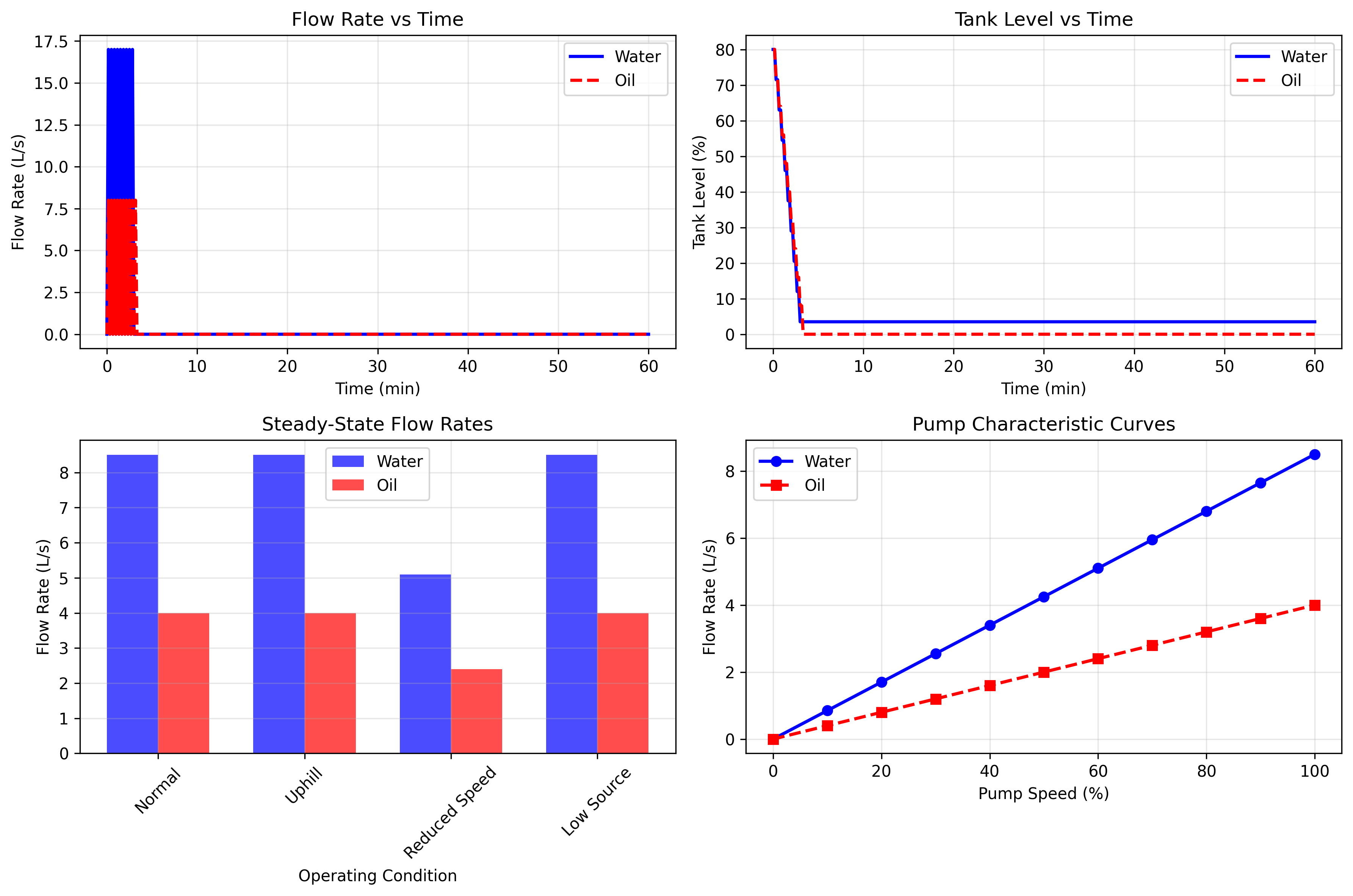
Dynamic response and steady-state analysis for water and oil transfer systems
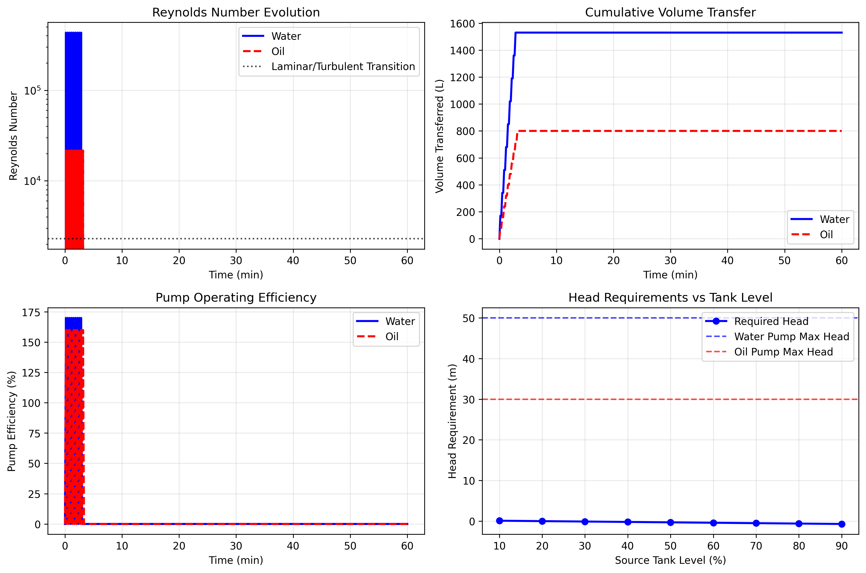
Detailed hydraulic analysis including Reynolds number evolution and system efficiency
Test Coverage
The test suite covers:
Model initialization and parameter validation
Steady-state calculations under various conditions
Dynamic behavior and system constraints
Edge cases and numerical stability
High viscosity fluid handling
Reynolds number regime transitions
Mass conservation verification
Pump head limitations
Run tests using:
pytest BatchTransferPumping_test.py -v
References
Perry, R.H., Green, D.W. (2019). “Perry’s Chemical Engineers’ Handbook”, 9th Edition, McGraw-Hill.
Crane Co. (2013). “Flow of Fluids Through Valves, Fittings, and Pipe”, Technical Paper 410.
Karassik, I.J., et al. (2008). “Pump Handbook”, 4th Edition, McGraw-Hill.
Coulson, J.M., Richardson, J.F. (2017). “Chemical Engineering Design”, Volume 6, 5th Edition.
Sinnott, R., Towler, G. (2019). “Chemical Engineering Design”, 6th Edition, Butterworth-Heinemann.
White, F.M. (2016). “Fluid Mechanics”, 8th Edition, McGraw-Hill.
Munson, B.R., et al. (2016). “Fundamentals of Fluid Mechanics”, 8th Edition, Wiley.
Note
This model assumes incompressible flow and single-phase operation. For two-phase flows or compressible fluids, additional models may be required.
Warning
Always verify that pump specifications match system requirements. Insufficient head can result in reduced flow rates or pump cavitation.